
I was first inspired for this project by a post that I saw on Hackaday of a 3D printed build of the Simpsons TV that played a random episode. ( Brandon Withrow has done a great build guide here if you’re interested. ) I chose Mystery Science Theater as it’s one of my favorite shows. I only started watching it when it moved to the SciFi Channel in the late 90’s and my parents finally splurged and got a mini satellite dish on the roof and all the channels that came with the basic package. I grew up watching it on a smallish 13″ CRT color TV, so I wanted to re-create that feeling and atmosphere.
Finding the right TV
To start I began crawling craigslist, Ebay and other second-hand item shops for a small, suitable CRT television. I was surprised to find that most titles listed words like “RETRO GAMING” or similar and commanded a higher price. It seems the retro gaming crowd has bumped up the cost of a legacy CRT television, which isn’t surprising since there aren’t any companies manufacturing CRT tubes today. Luckily I found this guy on Mercari for $35 and shipping.


It wasn’t in perfect condition, was missing a clear plastic faceplate, didn’t come with the original power supply/stand, and was missing the original antenna, but it powered up and functioned for what I was going to use it for. Originally in my mind, I was shooting for something in the common 13″ range, however, the screen size for the Sharp 3LS36 comes in at a tiny 3.5″, pretty minuscule for CRT standards. While researching this model on the internet, I had another stroke of luck and found the service manual which includes the schematic for the inside circuitry. If you’re looking for a TV for a similar project try and track down a service manual. The included schematic can be very useful when figuring out where (and where not!) to connect things to your Pi.

Parts List
- Raspberry Pi Zero 2 W or similar.
- You can use an original Zero, but it makes management and updates much harder.
- i2S Mono/Stereo DAC Decoder Breakout Module
- There are several options to choose from here, I went with a stereo module based on the PCM5102 chip from TI.
- Stereo Audio Amplifier
- This will bring the line level output from the I2S DAC to drive the embedded speakers. If you plan on using the line-in input on the TV, this is not needed.
- Speakers
- These are optional if you intend to use the auto circuitry in your TV. But I found these little guys put out some decent sound for their size.
- 12V to 5V DC Buck Converter
- This will depend on your TV and where you can pull power from. Since I’m running the TV set off a 12V DC Wall Wart, I’m using that with an adjustable DC-DC Buck converter to output 5V for the Pi and other parts. You may need to probe the board for a suitable source to use, this is where the schematic can come in handy.
- 38Khz IR Receiver module and IR Remote
- This is completely optional but makes control much easier for changing episodes, adjusting volume, etc.
Optional Parts
- Extra Buttons/Switches
- You can either re-purpose existing buttons (like I did for this build) or add new buttons or switches to control various functions. Your only limit is space/number of available GPIO pins on the PI.
- External Wifi Antenna
- Due to the noise inside the TV chassis and the availability of a antenna port that I could retrofit, I decided to add a u.FL connector to the Raspberry Pi coupled with a u.FL to RP-SMA pigtail and a Wifi antenna. This is of course completely optional and in no way affects the core function of the build.
Cramming it all in

When I finally got the case taken apart, I realized how little space I had to work with. I decided to put things mostly in the lower left corner area, away from the tube and other high voltage electronics.
Power
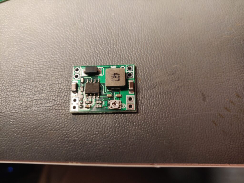
This was pretty basic as I took my DC-DC buck converter and found some input pads on the underside of the board where I could pull off 12V. I then added some output leads and a PH-SMT 2.0mm connector and socket soldered to the Raspberry Pi.

I threw a quick piece of shrink wrap over the module to prevent it from shorting out of the heatsink it would be living next to. While this heatsink is pretty large, I didn’t notice a significant amount of heat coming off of it so I wasn’t worried about the buck converter overheating either.
You’ll also notice I threw a small 10V 470uF capacitor on the 5V line to help filter out any noise on supply line and from the internal electronics of the CRT.
Audio
We have several options to consider for analog audio out from our Pi Zero. HDMI audio is a bit of a non starter since our TV was likely built before the standard existed. Our Pi Zero doesn’t have analog audio out like it’s larger cousins because that circuitry was removed to save space on the board. We could replicate that circuit, but that’s a bit more work/complexity than I have time for. So we’re left with either a USB to analog device, OR using I2S.

Connections
| PCM5102A Breakout | RASPBERRY PI |
| VIN | +5V |
| GND | GND |
| LCK | GPIO19 (Pin 35) |
| DIN | GPIO21 (Pin 40) |
| BCK | GPIO18 (Pin 12) |
| SCK | GND (See Note1) |

To save space I mounted the audio amp board directly on the back of the I2S DAC as the L,R, and AGND pins all lined up. I also pulled +5V and GND lines from the board as well. At this point you can hook up your speakers.
Raspberry Pi Setup
To get your Pi to start using this as your new audio output, you’ll need to modify your /boot/config.txt file to direct audio out to the the PCM5102A. Change the following:
#Uncomment or add
dtparam=i2s=on

#Comment this line if it exists
#dtparam=audio=on

#Append to your config.txt file
dtoverlay=hifiberry-dac
After a reboot you should be able to test out your new shiny sound machine:
pi@pinktv:~ $ aplay -l
**** List of PLAYBACK Hardware Devices ****
card 0: sndrpihifiberry [snd_rpi_hifiberry_dac], device 0: HifiBerry DAC HiFi pcm5102a-hifi-0 [HifiBerry DAC HiFi pcm5102a-hifi-0]
  Subdevices: 1/1
  Subdevice #0: subdevice #0
pi@pinktv:~ $


pi@pinktv:~ $ wget https://princessleia.com/sounds/MST3K/idea.wav
--2022-04-14 14:24:10--  https://princessleia.com/sounds/MST3K/idea.wav
Resolving princessleia.com (princessleia.com)... 2600:3c00::f03c:91ff:fe89:3d09, 104.237.128.178
Connecting to princessleia.com (princessleia.com)|2600:3c00::f03c:91ff:fe89:3d09|:443... connected.
HTTP request sent, awaiting response... 200 OK
Length: 55708 (54K) [audio/x-wav]
Saving to: ‘idea.wav’

idea.wav            100%[===================>]  54.40K   329KB/s    in 0.2s

2022-04-14 14:24:11 (329 KB/s) - ‘idea.wav’ saved [55708/55708]


pi@pinktv:~ $ aplay -V stereo idea.wav
Playing WAVE 'idea.wav' : Unsigned 8 bit, Rate 11025 Hz, Mono
##############                    +                | 66
If you’re not getting any sound, be sure to check your connections and configuration files for issues.
Video

This is pretty straight forward. You can output composite video out via two pins near the camera connector. I ran those and soldered them directly to the Video Input connector board. You should be able to find a similar RCA style connector depending on your type of TV.

Aaaand success! I have video output from the Pi. Not sure I’m going to be able to read that text though…

Setting up your video player
For the Pi, I’m booting a recent version of the Raspberry Pi OS. I am using the lite version WITHOUT any desktop GUI. This is to keep things light and fast.
First I added a custom boot screen, using a custom initfamfs image using some nifty code here: https://gitlab.com/DarkElvenAngel/initramfs-splash Follow those instructions to add whatever custom logo you’d like.
Next, we want to have our video player start automatically and play a random video on boot. I started tinkering with this for a while until I actually read the docs and realized that omxplayer is being deprecated in favor of VLC. So, first step, install VLC.
sudo apt install vlcNext, we’re going to use systemd and a service file to start VLC on boot and play a random episode.
[Unit]
Description=Random MST3K Player
Before=systemd-user-sessions.service
After=network-online.target
[Service]
TimeoutStartSec=0
WorkingDirectory=/media/sdcard/MST3K
ExecStart=cvlc --intf http --extraintf lirc -A alsa --vout mmal_vout --alsa-audio-device sysdefault --alsa-audio-channels 6 --lirc-file /home/pi/.lircrc --http-host=0.0.0.0 --http-port=9999 -LZ /media/sdcard/MST3K --http-password=mst3k
Type=simple
User=pi
ExecReload=/bin/kill -s HUP $MAINPID
ExecStop=/bin/kill -s QUIT $MAINPID
Restart=yes

[Install]
WantedBy=multi-user.target
Now, I’ll explain some of the details as best I can for this file.
NOTE: I used a 400GB Sandisk SD Card for this project so I could store all 10 seasons of MST3K. If your project has this amount of space, consider creating this directory on a separate partition on your SD card. That way if you end up having to pull the plug or some other ugly shutdown of your Pi, you won’t be waiting forever while the OS does a fsck of the entire SD card.
WorkingDirectoryThis should be the location of your media files, since we want to start VLC from here.ExecStart= cvlc....This is the main VLC command, I’ll touch on some of the switches used here- Interfaces: Since we don’t have a keyboard or a GUI, I add both the HTTP interface and the ability to use an IR remote to control VLC. See the IR remote section below for more details.
--vout mmal_voutThis tells VLC to use the hardware decoding builtin to the Broadcom chip We want this to keep our CPU nice and cool.-LZ /media/sdcard/MST3kThis switch tells VLC to randomly shuffle all the video files in the folder forever
User=piSpecifies the user that will run VLCExecReload and ExecStopThese are the commands used to stop or reload the service, just your basic kill command.
Now that you’ve got your service file all set, give systemd a reload and you’re good to go!
sudo systemctl daemon-reload
sudo systemctl start mst3k
Letting out the magical smoke
At this point I started to cram all these parts in the case, trying to be mindful of not shorting out anything and keeping clear of the high voltage areas. On one of these attempts as I powered the TV I a whiff of the tell-tale smell of heated silicon and IC packaging. I immediately pulled the power cord and opened up the case to determined what I killed.

After a few attempts to power the Raspberry Pi Zero back on, I could sense that one of the power chips failed and was acting as a short/small heater. So the Pi must have shorted out on something inside, and my first though was the large aluminum heat sink, which was attached to a power transistor. But that seems odd, I thought. It’s most likely grounded and the would have had to touch the one of the 5V/3.3V leads on the Pi.

As you can see the metal tab is connected directly to the heat sink and there’s no thermal paste, etc. A quick test with the meter showed an open between the heatsink and ground. Let’s see what the schematic says.
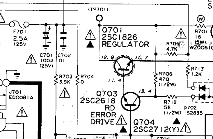
And the datasheet for the 2SC1826
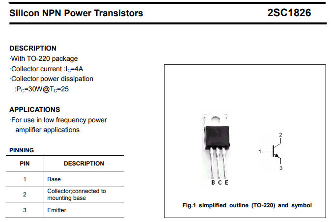
Awesome, so the collector and the mounting tab are the same electrically, and according to the schematic, that puts the heat sink at around 12V. My best guess is that one of the connectors (HDMI, USB) hit the heat sink and put the GND on the raspberry Pi at 12V, making all sorts of fun things happen.
So, I had two options.
Isolate the Pi and possibly other electronics somehow, maybe some Kapton tape I had on hand might work.
Or two, isolate the heat sink electrically from the collector on the power transistor but maintain thermal conductivity to keep from toasting other electronics. Since I had some thermal pads available from another project and wanted to improve the thermodynamics of the current set, I settled on option two.

What’s next?
So far the system runs pretty smoothly and sounds great. But there are a few items left that I’d like to improve
- Shutting down the Pi safely when I turn off the TV.
- Controlling volume and skipping episodes
Check out Part 2 and Part 3!